1System Comparison: Weight, Integration, and Mission Class
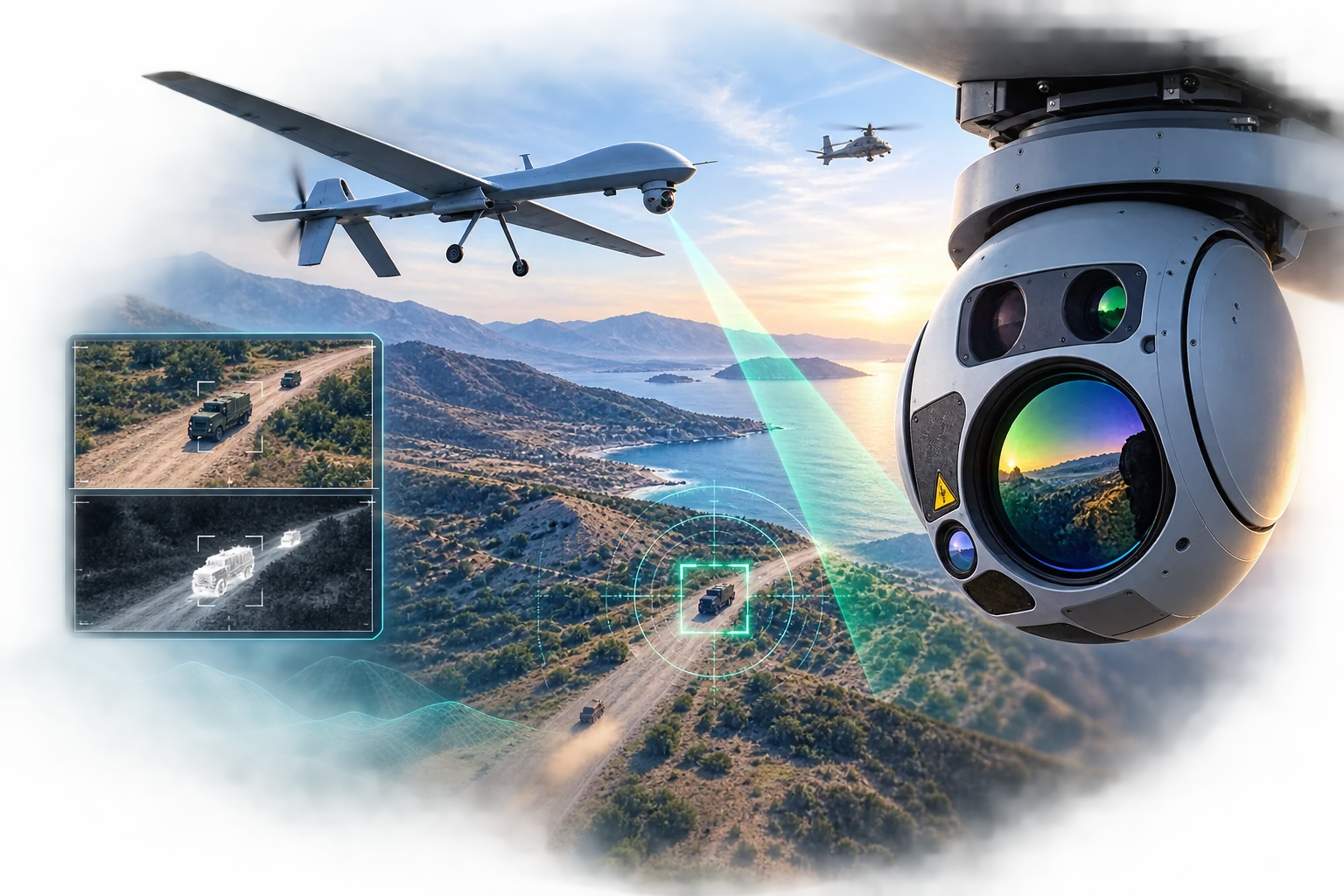
Selecting an EO/IR gimbal system is a multi-layered decision process for identifying the sensor solution that best fits the mission requirements of a UAV or other air platform. System weight, platform-integration capability, and intended mission class are the three central criteria in this process.
1.1 Weight: The Most Restrictive Parameter
Weight directly affects a UAV's payload budget and the other mission equipment it can carry. For example, within Bayraktar TB3's 280 kg payload capacity, a 54 kg ASELFLIR 500 uses about 19% of the budget and leaves 226 kg for munitions and other systems.
Physically, the systems fall into two main classes. ASELFLIR 600 (120 kg, 25 in) and WESCAM MX-25D (<118 kg, 25.7 in) are roughly 120 kg-class solutions for large air platforms with high payload capacity.
The lighter class includes ASELFLIR 500 (54 kg, 15 in), WESCAM MX-15D (48.7 kg, 15.5 in), and EUROFLIR 410 (<53 kg, ~16 in). At roughly 50 kg and 15–16 inches in diameter, these systems offer an integration advantage for platforms with lower payload budgets.
Why does gimbal diameter matter? A larger diameter can accommodate larger optical apertures and sensor packages that collect more detail at long range. The trade-off is greater system weight, volume, and integration burden on the platform. The 25-inch class can therefore benefit long-range missions on large platforms, while the 15–16-inch class offers a more balanced solution for lower payload budgets. Diameter alone does not determine performance; it must be considered together with optical aperture, sensors, and stabilization architecture.
1.2 Platform Integration
Platform integration covers physical installation as well as compatibility with power, data links, and the mission computer. WESCAM systems have a broad platform history across UAVs, helicopters, and aerostats. While ASELFLIR 600 is developed for large UAV/UCAV platforms, EUROFLIR 410 is a modular solution used on the Patroller UAS, NH90 and H160M helicopters, and special-mission aircraft.
EUROFLIR 410's standard interfaces, including ARINC 429, Ethernet, and RS-422, provide integration flexibility. In addition to technical compatibility, system selection should consider ITAR restrictions and ITAR-free procurement requirements.
1.3 Comparison Table
| Feature | ASELFLIR 500 | WESCAM MX-15D | EUROFLIR 410 | ASELFLIR 600 | WESCAM MX-25D |
|---|---|---|---|---|---|
| Baseline weight | 54 kg | 48.7 kg | <53 kg | 120 kg | <118 kg |
| Gimbal diameter | 15 in | 15.5 in | ~16 in | 25 in | 25.7 in |
| Class | Light/medium class | Light/medium class | Light/medium class | Heavy class | Heavy class |
| Primary mission class | ISR, targeting, and laser designation | Tactical ISR, targeting, and search and rescue | ISR, targeting, and multi-purpose missions | ISR, targeting, and laser designation | Long-range target acquisition and laser designation |
1.4 Conclusion: Selecting by Weight and Platform Class
The comparison identifies two core gimbal classes. ASELFLIR 500, WESCAM MX-15D, and EUROFLIR 410 suit the payload budgets of lighter platforms, at roughly 50 kg and 15–16 inches in diameter. ASELFLIR 600 and WESCAM MX-25D belong to the roughly 120 kg, 25-inch class intended for large platforms with high payload capacity. Selection should therefore identify the class that fits the platform's weight budget and required sensor capability—not simply the most advanced system.
2Applying Closed-Loop Control to Gimbal Stabilization
The general principle of closed-loop control is covered in our autopilot-balance article. In an EO/IR gimbal, it is applied through IMU data and gimbal motors to compensate for platform motion and keep the line of sight on the target.
The critical measure here is not merely whether the image appears steady, but how precisely the optical axis can remain on target. Sub-5 microradian performance figures cited for ASELSAN's ASELFLIR 600 and next-generation ASELFLIR 500, and similarly for WESCAM's MX-25/MX-25D class, show how that precision scales with range:
| Angular error | Deviation at 1 km | Deviation at 10 km |
|---|---|---|
| 1 µrad | About 1 mm | About 1 cm |
| 5 µrad | About 5 mm | About 5 cm |
| 10 µrad | About 1 cm | About 10 cm |
A 5 cm deviation at 10 km may appear insignificant, but keeping the laser-designation spot fixed, identifying a target at high magnification, and retaining automatic-tracking lock all depend on it. When stabilization weakens, the laser spot can drift, the image can blur, and the tracker can lose the target. Microradian-level stability therefore enables a UAV not merely to observe, but to perform precision-targeting missions reliably.
Rotor vibration, aerodynamic disturbance, and sudden platform manoeuvres can otherwise reach the sensor directly, producing blurred or unstable imagery. Systems mitigate this effect at two levels: mechanical gimbal axes make coarse corrections to keep the camera on target and compensate for large platform motion, while fine corrections are made through optical mirrors or additional isolation layers, depending on the architecture. In the ASELFLIR family, four-axis mechanical stabilization works with two-axis optical stabilization, delivering six-axis performance in total. In the WESCAM MX-25 class, a fifth axis helps isolate high-frequency vibration and sudden structural shocks. The following comparison summarizes the difference between these approaches.
2.1 Mechanical and Hybrid Stabilization Architectures
The five-axis mechanical approach in the WESCAM MX-25 class and the 4-mechanical-plus-2-optical-axis hybrid approach in the ASELFLIR family address the same problem through different engineering methods. In a mechanical system, gimbal rings and isolation layers physically steer and isolate the optical block. In a hybrid architecture, mechanical rings correct coarse motion while internal moving mirrors optically compensate for fine, rapid deviations in the light path.
| Feature | WESCAM MX-25 class | ASELFLIR 4+2-axis hybrid architecture |
|---|---|---|
| Damping method | Mechanical gimbal rings and isolation layers | Mechanical rings + two-axis optical mirror stabilization |
| Fine correction | The optical block and gimbal mechanism move together | Moving mirrors correct small deviations in the light path |
| Engineering outcome | Smooth target tracking and strong mechanical isolation | Low-inertia mirrors may provide faster response to high-frequency micro-vibration |
2.2 Architecture Selection and Trade-Offs
| Architecture | Better-suited scenario | Primary trade-off |
|---|---|---|
| ASELFLIR 4+2 hybrid | High-frequency micro-vibration, long range, and precision laser designation | Optical alignment, calibration, and control software are more complex |
| WESCAM five-axis mechanical | Wide-area ISR on large platforms, smooth pan/tilt tracking, and physical isolation | Mass/inertia, volume, and mechanical-maintenance requirements may be greater |
The final choice should consider the platform's vibration profile, payload budget, sensor package, and maintenance concept together—not stabilization architecture alone.
3Practical Effects of Stabilization
A 5 cm excursion on a target at 10 km may appear small at first, but in EO/IR systems that stability directly affects three critical operational outcomes. Keeping a laser-designation spot fixed is necessary for laser-guided munitions to follow a smooth path; small angular vibration at high magnification can blur the image and hinder target identification; and pixel-based automatic trackers can lose lock when the image shifts abruptly. The following scenarios explain these effects in practical terms.
3.1 Image Quality in High-Vibration Environments
Helicopters generate a more complex vibration spectrum than most fixed-wing aircraft. Rotor-induced micro-vibrations and aerodynamic disturbances can make imagery from an inadequately stabilized turret blurred or difficult to interpret. WESCAM's laser stabilization and internal vibration isolation, together with ASELSAN's six-axis (4+2) line-of-sight stabilization, are designed to mitigate this problem.
The result is a more continuous and stable image stream for the operator?and better input for target detection, tracking, and AI-assisted image analysis.
3.2 Target Tracking at High Magnification
High magnification amplifies even minor platform vibration. At long range, a milliradian-scale angular deviation can move a target out of the field of view. Stable imagery allows an operator to maintain high magnification while preserving details needed for identification. ASELFLIR multi-target tracking follows multiple targets in software within the same field of view, while the physical gimbal remains pointed along a single line of sight. This distinction matters for target prioritization and tracking continuity in complex environments.
3.3 Maintaining Line of Sight During Laser Designation
Laser designators project a narrow beam toward a target so compatible precision-guided munitions can home on the designated point. Mechanical stabilization maintains alignment of the designator axis despite host-platform motion. This is why stabilization performance affects the complete detect?track?designate?engage chain, not merely image comfort.
4Mechanical versus Digital Stabilization
Imagine filming with a phone while running. A motorized gimbal counteracts your hand movement, so the camera remains physically stable and the video stays sharp and wide. With digital stabilization, onboard software crops and shifts the live video to reduce apparent motion. It can make footage look steadier, but cropping narrows the field of view and cannot restore detail lost to motion blur during capture.
UAV EO/IR systems follow the same principle: mechanical stabilization physically keeps the optics stable, while digital stabilization electronically corrects the live video stream. The following scenarios show the operational difference.
4.1 High-Vibration Environment
Mechanical: the IMU detects motion and control and motor drivers apply opposite-direction correction in sub-millisecond-scale cycles. Physically isolating the optics helps keep light stable on the sensor during exposure, preserving a clear, wide field of view.
Digital: an onboard processor shifts and crops the live video stream in real time. If vibration has already caused motion blur during exposure, software cannot restore the lost detail; cropping also narrows the field of view and reduces usable pixels.
4.2 Long-Range Identification ? 20 km
Mechanical: a stable view lets the operator use high optical magnification and preserve details on a distant vehicle. Digital: at this range the target occupies few pixels, so cropping can further reduce useful detail. If vibration has caused motion blur during exposure, digital processing cannot restore the original details needed for identification.
4.3 Fast Target Tracking
Mechanical: the gimbal and tracking controller can rapidly redirect the line of sight and retain the target near frame centre. Digital: electronic correction cannot physically redirect the optical axis; its correction margin may be exceeded during fast motion and further processing can add latency. Digital stabilization is therefore a complementary layer, not a substitute for high-performance mechanical stabilization.
Stabilization is not a secondary feature that merely makes imagery more comfortable to watch; it is fundamental to mission reliability. Microradian-level line-of-sight stability enables operators to distinguish detail at long range, helps automatic tracking retain lock, and keeps the laser-designation point on target.
That is why the right choice is not simply the system with higher resolution or larger optics. It must fit the platform's vibration profile, payload budget, and required targeting precision. Mechanical stabilization provides the physical stability; digital stabilization is a useful supporting layer, but cannot restore motion-blurred or lost image detail after capture.