How Does an Autopilot Keep a UAV Balanced?
Spoiler: Much Faster Than You Think!
When watching an unmanned aerial vehicle (UAV) glide smoothly through the sky, you might think to yourself, "What an advanced system, managing everything on its own." In reality, however, most of today's UAVs are not artificial intelligence systems that reason like humans. Instead, they continuously analyze data from sensors, run predefined control algorithms, and sustain stable flight using commands generated by these algorithms.
So how do they achieve this? Let's explore how a UAV maintains its balance in the air and examine the control algorithms behind the autopilot.
Why Do UAVs Constantly Lose Balance?
Consider a fixed-wing UAV flying straight and level. While it may appear perfectly stable from the outside, it is actually constantly battling forces that disrupt its equilibrium. The main factors affecting UAV stability include:
Wind & Turbulence
Continuously changing air currents can push the UAV off course or cause unexpected tilting.
Propulsion & Control System
Thrust produced by the engine and aerodynamic forces from control surfaces may exhibit minor variations over time.
Center of Gravity
Fuel consumption, payload position, or minor fuselage imbalances can affect flight characteristics.
Sensor Errors
Small measurement errors in accelerometers and gyroscopes, or electronic noise, can create deviations requiring constant correction.
Although each of these effects may seem minor individually, they occur continuously during flight. Therefore, the autopilot analyzes sensor data without interruption and generates correction commands hundreds of times per second to maintain stable flight.
What Is an IMU (Inertial Measurement Unit) and How Does It Work?
For a UAV to maintain balance, it must first perceive its own movement. Just like the inner ear that maintains human balance, the autopilot has a sensor package called IMU (Inertial Measurement Unit).
The IMU consists of two primary sensors:
Gyroscope
Measures how fast the UAV rotates around its Roll, Pitch, and Yaw axes (angular velocity). This allows instantaneous detection of sudden directional changes.
Accelerometer
Measures the UAV's linear acceleration. By referencing the gravity vector, it helps estimate orientation, especially during stationary or slow movements.
The autopilot does not use data from these sensors individually. Instead, it combines measurements from different sensors to obtain a more reliable result. This process is called Sensor Fusion. Thus, the UAV's orientation in space (attitude) is estimated with high accuracy in real-time.
How Does Closed-Loop Control (Feedback Control) Work?
Here arises an important question:
What would happen if the autopilot simply commanded the motors to "spin at this speed"?
This approach is called Open-Loop Control. Just as a person walking blindfolded cannot notice obstacles on the road, a UAV moving solely based on pre-given commands could deviate from its course due to wind or turbulence. This is because open-loop systems do not continuously monitor the outcome.
Therefore, modern UAV autopilots use Closed-Loop Control (Feedback Control).
The autopilot does not settle for giving a one-time command. In every control cycle, it compares the target orientation with the current orientation and generates a new correction command based on the error.
Error = Target Orientation − Current Orientation
The goal is to minimize the difference between the target orientation and the current orientation as close to zero as possible.
The entire process is illustrated in the closed-loop control diagram below:
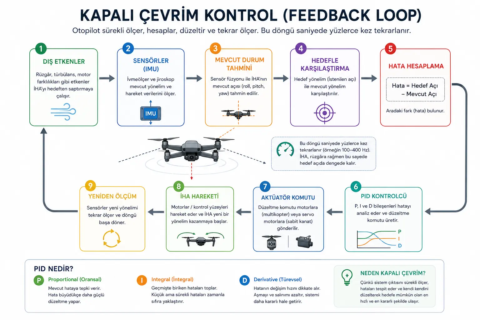
Figure 1. Simplified representation of the closed-loop (feedback) control cycle used in UAV autopilots.
This feedback loop typically operates at 100–400 Hz. In other words, the autopilot reads sensors hundreds of times per second, calculates errors, and generates new correction commands to maintain stable flight.
What Is PID Control and How Does It Work in UAVs?
Once the error is calculated, the PID controller takes over.
PID analyzes the error between the target and current state to calculate the optimal correction command to be sent to motors or control surfaces.
It is quite easy to understand this logic by thinking of the Cruise Control system found in automobiles.
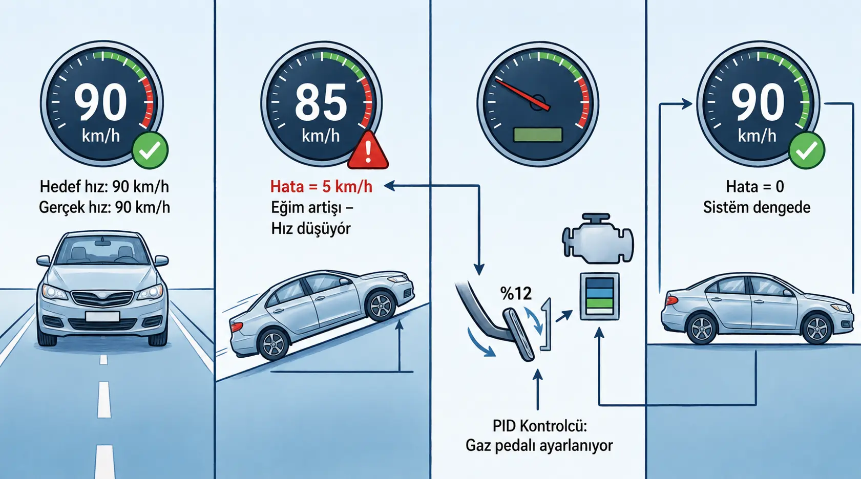
🚗 Example: Cruise Control
The vehicle is set to 90 km/h. When speed drops to 85 km/h due to an incline, the system detects this error, increases throttle, and brings the vehicle back to the target speed. The PID controller works on the same principle in UAVs, continuously calculating the error between target and current states to apply necessary corrections.
The UAV autopilot operates on the same logic. After calculating the error, the PID controller attempts to correct it using three distinct components.
Control Output = P + I + D
The PID controller creates the correction command by evaluating the current error (P), past errors (I), and the rate of change of the error (D) together.
Proportional
Reacts to the current error. As the error grows, the correction command increases proportionally.
Integral
Sums up small accumulated errors from the past and eliminates persistent deviations over time.
Derivative
Examines how fast the error is changing. Helps reduce overshoot, oscillation, and instability.
PID's greatest advantages are its simple structure, ease of adaptation to different systems, and reliability when properly tuned. Therefore, it remains widely used in many control systems today, from UAVs to industrial robots.
🌍 Systems Using PID
UAV Autopilots
Passenger Aircraft
Cruise Control
Industrial Robots
CNC Machines
Temperature Control
What Do Roll, Pitch, and Yaw Mean?
A UAV's orientation in three-dimensional space is described by three fundamental rotation axes. The autopilot continuously evaluates sensor data along these axes to maintain the aircraft's desired attitude during flight.
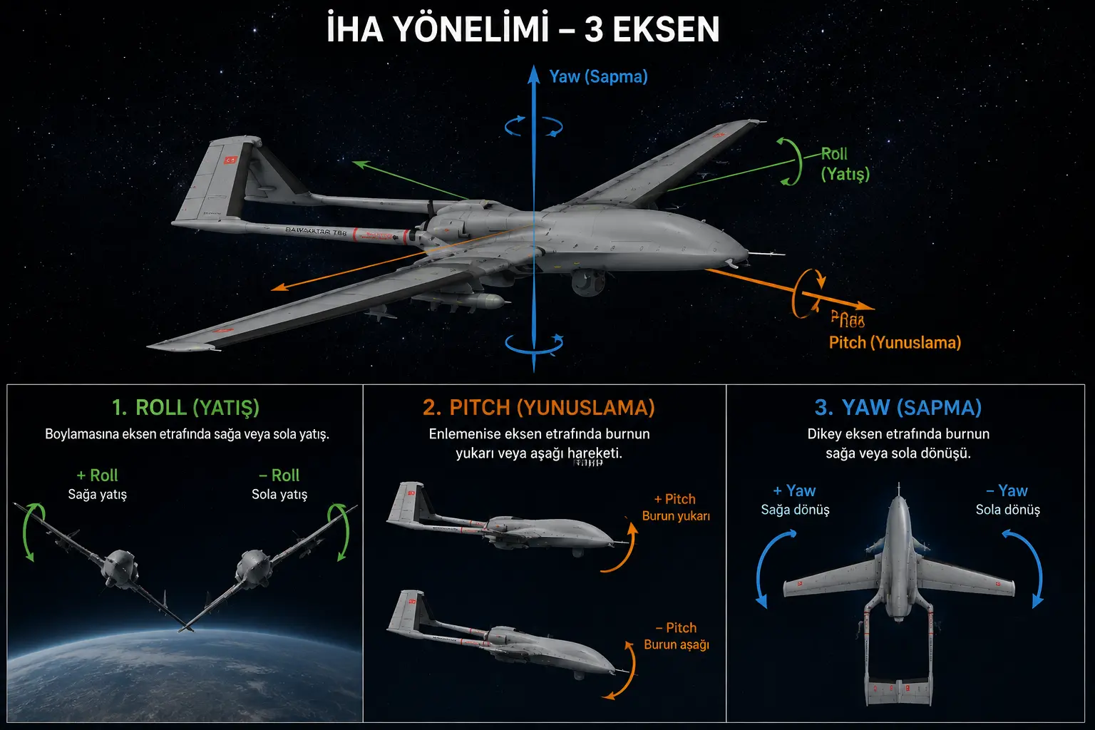
Figure 2. The three fundamental rotation axes of a UAV: Roll, Pitch, and Yaw.
Roll
Rotation about the longitudinal axis, causing the aircraft to tilt to the left or right.
+ Right roll
− Left roll
Pitch
Rotation about the lateral axis, moving the aircraft's nose upward or downward.
+ Nose up
− Nose down
Yaw
Rotation about the vertical axis, turning the aircraft's nose to the left or right.
+ Right yaw
− Left yaw
How Does the Autopilot Apply Control Commands?
Correction commands calculated by the PID controller have no meaning on their own. These commands must be converted into physical movement of the UAV.
Aileron
Moves control surfaces to provide Roll control.
Elevator
Moves the elevator surface to provide Pitch control.
Rudder
Moves the rudder surface to provide Yaw control.
The autopilot sends commands to servo motors that move these control surfaces, ensuring the UAV remains in the desired orientation.
How Many Times Per Second Does the Autopilot Calculate?
It takes an average human 200 milliseconds to perceive an unexpected situation and react. Modern flight control systems can complete dozens of control cycles within that same timeframe.
The sensor reading frequency and the PID control loop frequency are not the same. While sensors generate data at higher speeds, the control algorithm processes this data at specific intervals to create correction commands.
| Operation | Example Frequency |
|---|---|
| Reading IMU sensors | 8 kHz (8000 Hz) |
| PID control loop | 400 Hz |
These values may vary depending on the flight controller, sensors, and software architecture used.
Before you blink once, the autopilot has read sensors thousands of times, executed hundreds of control loops, and generated new commands to maintain the UAV's balance.
Conclusion
A UAV's stable flight does not rely on a single sensor or a single algorithm. Instead, it is achieved through an advanced flight control system in which the IMU, sensor fusion, closed-loop control, and PID algorithms work together. By continuously analyzing sensor data hundreds of times per second and making instant corrective adjustments, the autopilot enables the UAV to maintain stable, accurate, and reliable flight even in the presence of wind, turbulence, and other external disturbances.